Technology > The processes take place on different scales > Scale 3: The individual fuel cell and its porous layers
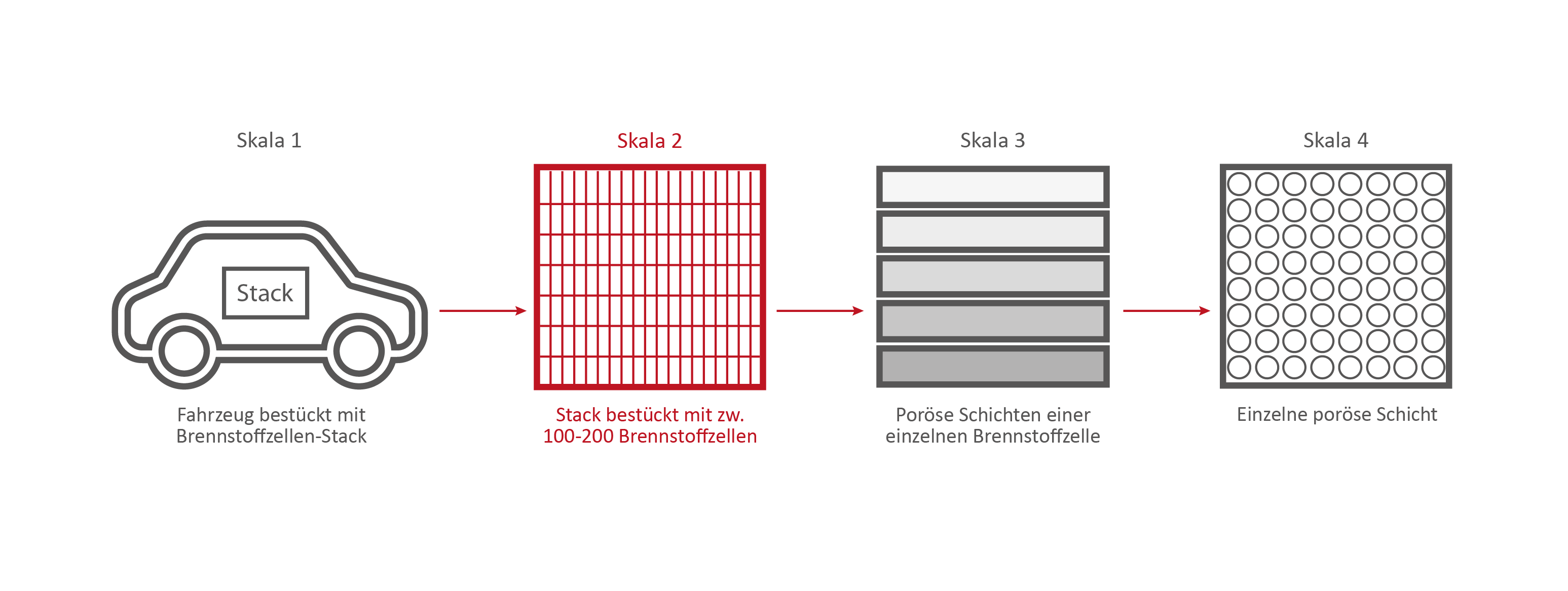
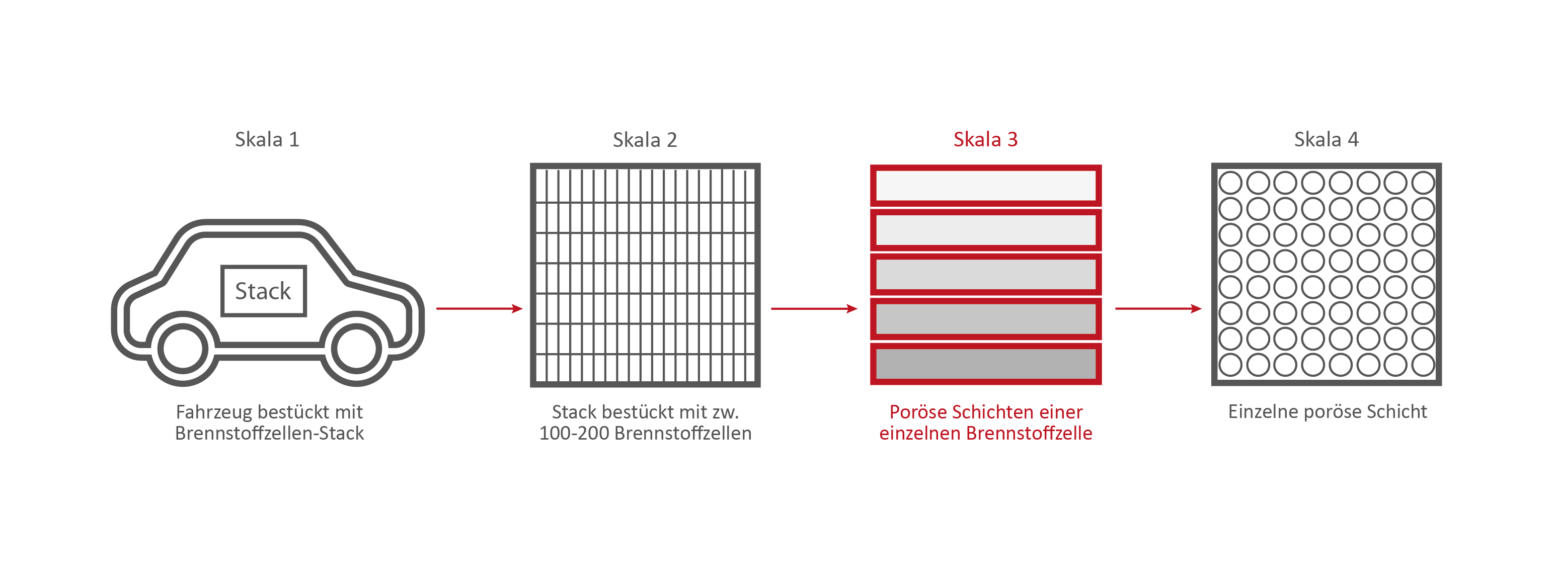
Scale 3: The individual fuel cell and its porous layers
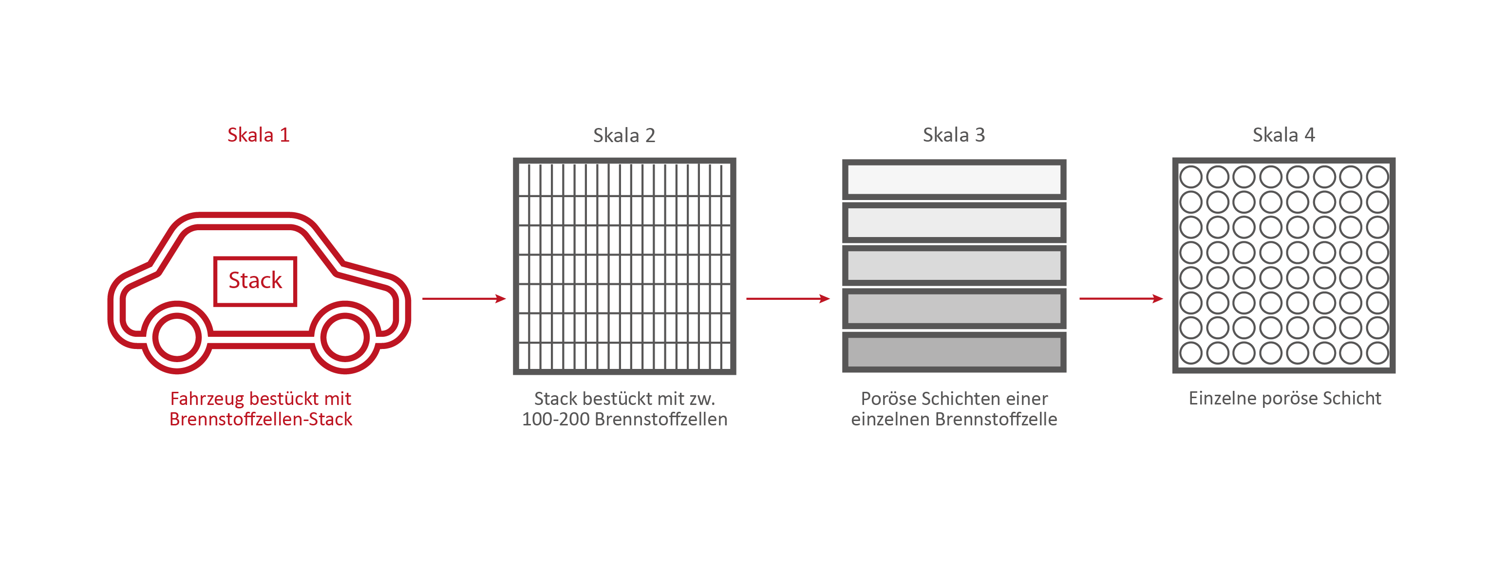
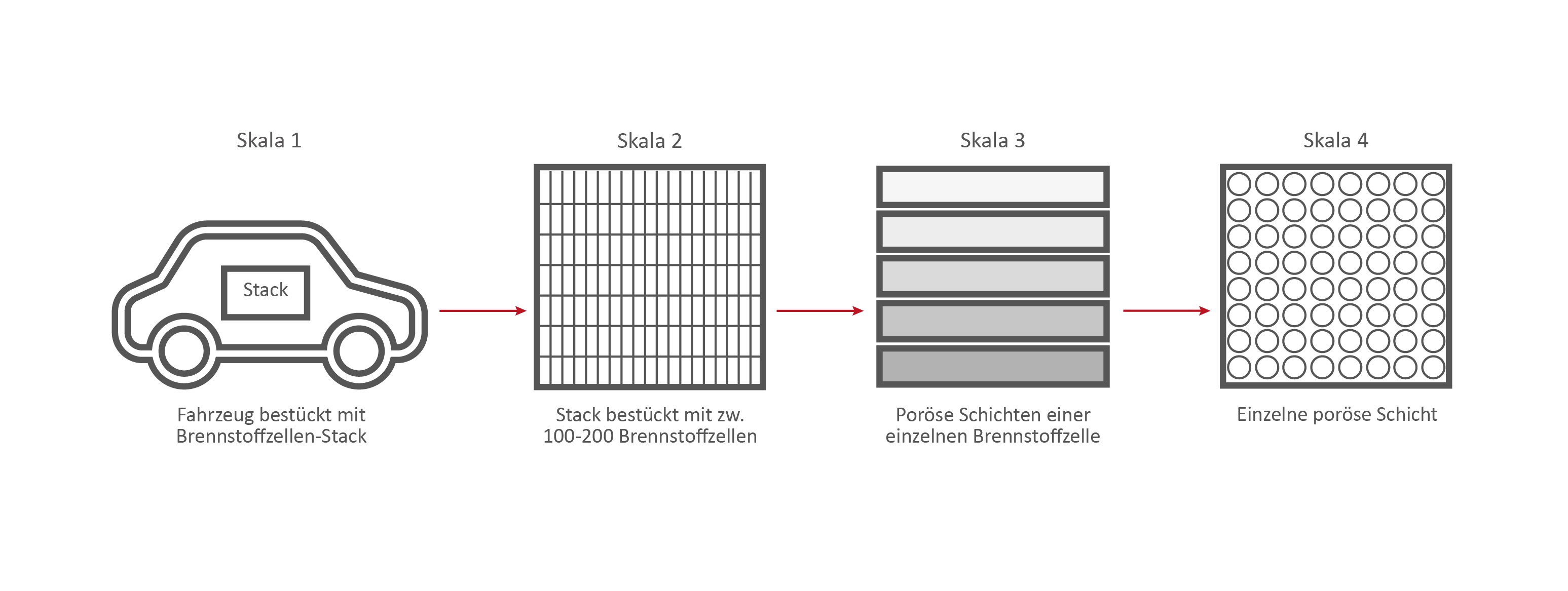
These processes take place on different scales. Credits: University of Stuttgart / SFB 1313
The research on the PEM (polymer electrolyte membrane) fuel cell serves as an example. It consists of nine porous and non-porous layers and materials with different properties.
A single fuell cell is very thin, less than 2 cm thick and about 30 cm long.
If the PEM fuel cell is opened, the nine different layers become visible.
The nine different layers of the PEM fuel cell Credits: University of Stuttgart / SFB 1313 / Cynthia Michalkowski
Enumeration of the 9 layers of the PEM fuel cell
1) Anode side: Gas channels – Channel structure (not porous). Material: metal or ceramics
4) Anode side: CL = Catalyst Layer (nano-porous). Very fine scale, but the transport processes are the same as in a porous medium. Material: carbon particle and Ionomer chains with platinum as catalyze
5) PEM = Polymer Electrolyte Membrane (more or less porous). The transport is chemical rather than comparable to a porous medium. Material: Nafion
6) Cathode side: CL – see anode side
7) Cathode side: MPL – see anode side
8) Cathode side: GDL – see anode side
9) Cathode side: Gas channel. Classical channel structure (not porous), but can also be expanded metal or similar material that can be interpreted as a porous medium. Material: metal or ceramics.
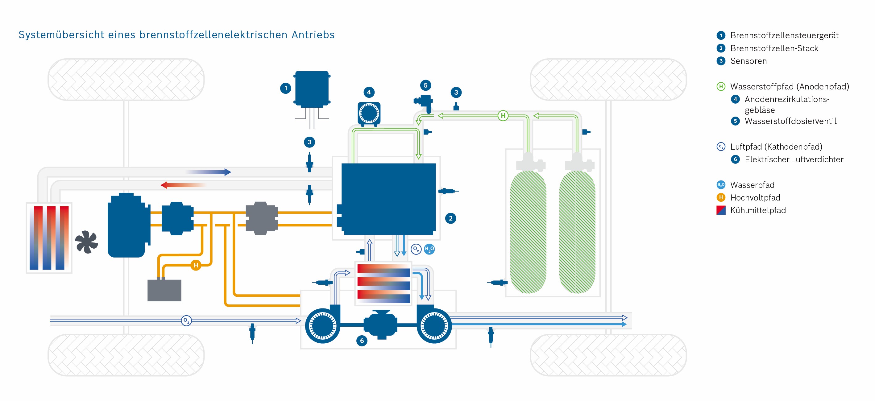
Hydrogen (H2) and oxygen (O2) (from the air) pass through the porous layers of the fuel cell and finally react to water (H2O) that is transported out of the cell. A “transport” of hydrogen and oxygen through the porous layers of the fuel cell takes place.
Reaction equation of water: 2 H2 + O2 ⇌ 2 H2O
This reaction and the interaction of the various systems in the vehicle generate electrical energy, which ultimately drives the vehicle.
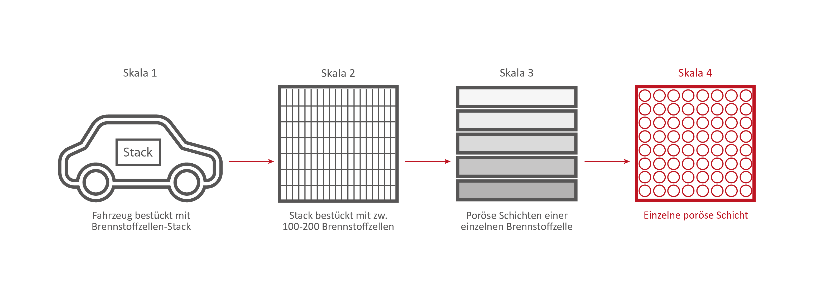
Technology > The processes take place on different scales > Scale 4: A single fuel cell layer
Skala 4: Eine einzelne Brennstoffzellen-Schicht
These processes take place on different scales. Credits: University of Stuttgart / SFB 1313
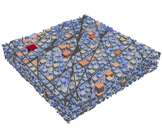
If we take a closer look at one of the nine layers under the microscope – the GDL layer – the network-like structure and cavities become visible. This layer is porous. Hydrogen, oxygen and water can flow through it.
This is the GDL layer, transferred into a computer model. Researchers are able to create simulations with the help of models. This simulation shows how and where exactly hydrogen, oxygen and water flow through the layer.
GDL Pore network Credits: University of Stuttgart / SFB 1313 / Cynthia Michalkowski
Technology > The processes take place on different scales > Simulating processes in the fuel cell
Simulating processes in the fuel cell
Simulations are important in the research of fuel cells because they help to make processes in the fuel cell visible. With their help, researchers can understand the function of the porous layers. They understand how the transport of water, oxygen and hydrogen happens and whether they have to optimize the layers. Should they use a different material or structure? The knowledge they generate from the simulations can, for example, help to reduce costs during the vehicle production process.
Model of the GDL layer of the fuel cell Credits: University of Stuttgart / SFB 1313 / Cynthia Michalkowski
This example shows a model of a fuel cell GDL layer. With the help of this model it is possible to simulate the water proportion in the pores. The water is pressed through the porous layer and exits at the marked points
Technology > The processes take place on different scales > Simulating processes in the fuel cell > In-depth text simulation
In-depth text simulation:
During the reaction of hydrogen and oxygen, water is produced. The produced water needs to be removed from the catalytic layer, where the reactions take place, to keep enough space available for new reactants. If there is not no exchange, an equilibrium evolves such that no electric energy is produced by the reactions. To ensure a continuous energy supply, the produced water is removed through the cathode of the cell. The water is transported through the different, porous layers. Water can be present in liquid or vapor form, due to condensation and evaporation. In this simulation, we consider the liquid water transport through the hydrophobic gas diffusion layer. This means, the water is the non-wetting phase on this coated carbon fiber material. On the pore-scale, this is an inhomogeneous and anisotropic structure. To investigate the water transport though this layer and to predict the break-through locations of the liquid water on the surface of the porous layer, a geometrical simplified model is used. The pore space of the material is represented by a network of pore bodies (network nodes) and pore throats (network connections). This allows an efficient calculation of the ongoing transport processes in the gas diffusion layer including the pore-scale effects. The simulation shows the locations, where liquid water first leaves the fibrous material. With this information, the gas diffusion layer structure can be optimized for the desired water distribution.
Pretty Porous 01
01
The processes take place on different scales
These processes take place on different scales. Credits: University of Stuttgart / SFB 1313
Our website uses cookies to garantuee the best user experience possible. More information about cookies can be found in our privacy policy. Please accept the usage of cookies to continue browsing our website.